Magnetic Effects of Electric Current
Magnetic Effects of Electric Current :
EFFECTS OF ELECTRIC CURRENT
There are mainly two kinds of effect of Electric Current. These are
- Heating Effect
- Magnetic Effect
Heating Effect :When an electric current flows through a wire, the wire gets heated. It is the heating effect of current. This effect has many applications.
- It is used in room heater or Electric heaters.
- The filament of an electric bulb gets heated to such a high temperature that it starts glowing.
- Wires made from some special materials melt quickly and break when large electric currents are passed
through them. These wires are used for making electric fuses.
Magnetic Effect: when electric current passes through a wire, it behaves like a magnet. This is the magnetic effect of the electric current.
- An electric current can be used to make magnets.
- When electric current flows through a current carrying coil of an insulated wire wrapped around a piece of
iron it behaves like a magnet.When the electric current is switched off, the coil generally loses its magnetism. Such coils are called electromagnets.
MAGNETIC FIELD AND FIELD LINES
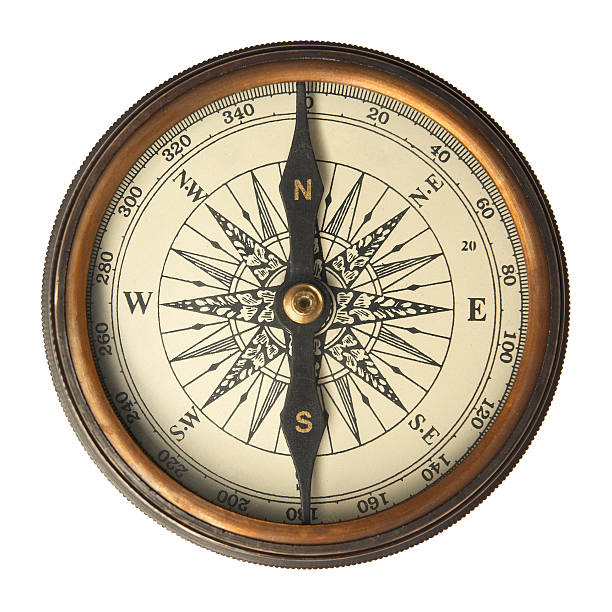
A compass needle is a small magnet. Its one end, which points towards north, is called a north pole, and the other end, which points towards south, is called a south pole.

A magnetic field exists in the region surrounding a magnet, in which the force of the magnet can be detected.
Field lines are used to represent a magnetic field. A field line is the path along which a hypothetical free north pole would tend to move.
Characteristics
Field lines are shown closer together where the magnetic field is greater.
Magnetic field is a quantity having both direction and magnitude. The direction of the magnetic field is taken to be the direction in which a north pole of the compass needle moves inside it. Therefore it is taken by convention that the field lines emerge from north pole and merge at the south pole. Inside the magnet, the direction of field lines is from its south pole to its north pole. Thus the magnetic field lines are closed curves.
MAGNETIC FIELD DUE TO A CURRENT-CARRYING CONDUCTOR
An electric current through a metallic conductor produces a magnetic field around it. To determine the direction of the magnetic field associated with a current-carrying conductor we use Right Hand Thumb Rule.
Right-Hand Thumb Rule

Imagine that you are holding a current-carrying straight conductor in your right hand such that the thumb points towards the direction of current.
Then your fingers will wrap around the conductor in the direction of the field lines of the magnetic field.
FORCE ON A CURRENT-CARRYING CONDUCTOR IN A MAGNETIC FIELD
An electric current flowing through a conductor produces a magnetic field which exerts a force on a magnet placed in the vicinity of the conductor.
French scientist Andre Marie Ampere (1775–1836) suggested that the magnet must also exert an equal and opposite force on the current-carrying conductor.
The direction of the Force on the conductor depends upon the direction of current and the direction of the magnetic field
If the direction of the field and that of the current are mutually perpendicular to each other, then the force acting on the conductor will be perpendicular to both and will be given by Fleming’s left-hand rule.
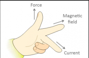
According to Fleming’s left-hand rule, stretch the thumb, forefinger and middle finger of your left hand such that they are mutually perpendicular. If the first finger points in the direction of magnetic field and the second finger in the direction of current, then the thumb will point in the direction of motion or the force acting on the conductor.
ELECTRIC MOTOR
Electrical energy is converted into mechanical energy by using an electric motor. Electric motor works on the basis of rule suggested by Marie Ampere and Fleming’s Left Hand Rule.

Structure
An electric motor consists of a rectangular coil ABCD of insulated copper wire placed between the two poles of a magnetic field such that the arm AB and CD are perpendicular to the direction of the magnetic field.
The ends of the coil are connected to the two halves P and Q of a split ring. The inner sides of these halves are insulated and attached to an axle.
The external conducting edges of P and Q touch two conducting stationary brushes X and Y.
Working
Current in the coil ABCD enters from the source battery through conducting brush X and flows back to the battery through brush Y.
Current in arm AB of the coil flows from A to B. In arm CD it flows from C to D, that is, opposite to the direction of current through arm AB.
On applying Fleming’s left hand rule. We find that the force acting on arm AB pushes it downwards while the force acting on arm CD pushes it upwards.
Thus the coil and the axle O rotate anti-clockwise. At half rotation, Q makes contact with the brush X and P with brush Y. Therefore the current in the coil gets reversed and flows along the path DCBA.
The reversal of current also reverses the direction of force acting on the two arms AB and CD.
Thus the arm AB of the coil that was earlier pushed down is now pushed up and the arm CD previously pushed up is now pushed down.
Therefore the coil and the axle rotate half a turn more in the same direction. The reversing of the current is repeated at each half rotation, giving rise to a continuous rotation of the coil and to the axle.
NOTE: A device that reverses the direction of flow of current through a circuit is called a commutator. In electric motors, the split ring acts as a commutator.
The commercial motors use
- An electromagnet in place of permanent magnet;
- Large number of turns of the conducting wire in the current carrying coil
- A soft iron core on which the coil is wound. The soft iron core, on which the coil is wound, plus the coils, is called an armature. This enhances the power of the motor.
ELECTROMAGNETIC INDUCTION
When a conductor is placed in a changing magnetic field, some current is induced in it, this phenomenon is called Electromagnetic Induction.
Whenever there is a change in magnetic field in the region of coil, current flows.
This law of ElectroMagnetic Induction was given by Michael Faraday.
The induced current is found to be the highest when the direction of motion of the coil is at right angles to the
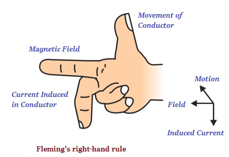
magnetic field. In this situation, we can use a simple rule to know the direction of the induced current called Fleming’s right-hand rule.
Fleming’s right-hand rule: Stretch the thumb, forefinger and middle finger of right hand so that they are perpendicular to each other. If the forefinger indicates the direction of the magnetic field and the thumb shows the direction of motion of conductor, then the middle finger will show the direction of induced current.
Galvanometer : It is an instrument that can detect the presence of a current in a circuit. If pointer is at zero (the centre of scale) then there will be no flow of current.
If the pointer deflect on either side right or left, this will show the direction of current. Represented by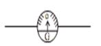
ELECTRIC GENERATOR
Electric Generator is based on the principle of electromagnetic induction.In an electric generator, mechanical energy is used to rotate a conductor in a magnetic field to produce electricity.

Structure
An electric generator consists of a rotating rectangular coil ABCD placed between the two poles of a permanent
magnet.
The two ends of this coil are connected to the two rings R1 and R2.
The inner side of these rings are made insulated. The two conducting stationary brushes B1 and B2 are kept pressed
separately on the rings R1 and R2.
The two rings R1 and R2 are internally attached to an axle. The axle may be mechanically rotated from outside to rotate the coil inside the magnetic field.
Outer ends of the two brushes are connected to the galvanometer to show the flow of current in the given external circuit.
Working
When the axle attached to the two rings is rotated such that the arm AB moves up (and the arm CD moves down) in the magnetic field produced by the permanent magnet.
Let us say the coil ABCD is rotated clockwise in the arrangement. By applying Fleming’s right-hand rule, the induced currents are set up in these arms along the directions AB and CD. Thus an induced current flows in the
direction ABCD.
If there are larger numbers of turns in the coil, the current generated in each turn adds up to give a large current through the coil. This means that the current in the external circuit flows from B2 to B1
After half a rotation, arm CD starts moving up and AB moving down.
As a result, the directions of the induced currents in both the arms change, giving rise to the net induced current in the direction DCBA. The current in the external circuit now flows from B1 to B2.
Thus after every half rotation the polarity of the current in the respective arms changes.
Such a current, which changes direction after equal intervals of time, is called an alternating current. This device
is called an AC generator.
To get a direct current (DC, which does not change its direction with time), a split-ring type commutator must be used. With this arrangement, one brush is at all times in contact with the arm moving up in the field, while the other is in contact with the arm moving down.
Thus a unidirectional current is produced. The generator is thus called a DC generator.
The difference between the direct and alternating currents is that the direct current always flows in one direction, whereas the alternating current reverses its direction periodically.
Most power stations constructed these days produce AC. In India, the AC changes direction after every 1/100 second, that is, the frequency of AC is 50 Hz.
DOMESTIC ELECTRIC CIRCUITS
In our homes, we receive supply of electric power through a main supply, either supported through overhead electric poles or by underground cable.
In our homes, the electric power supplied is of potential difference V = 220V and frequency 50Hz.

It consist of three wires :–
(1) Wire with red insulation cover – LIVE WIRE (POSITIVE) Live wire is at high potential of 220V
(2) Wire with black insulation cover – NEUTRAL WIRE(NEGATIVE) Neutral wire is at zero potential Therefore, the potential difference between the two is 220V.
(3) Wire with Green insulation cover – EARTH WIRE
It is connected to a copper plate deep in the earth near house.
The metallic body of the appliances is connected with the earth wire as a safety measure.
These wires supply electricity to separate circuits within the house. Often, two separate circuits are used, one of
15 A current rating for appliances with higher power ratings such as geysers, air coolers, etc and other of 5 A current rating for bulbs, fans, etc.
Earth wire provide a low resistance to the current hence any leakage of current to the metallic body of the appliances, keep its potential equal to that of earth. That means zero potential and the user is saved from severe electric shock.
Point to be noted in Domestic Circuit
(a) Each appliance has a separate switch of ON/OFF
(b) In order to provide equal potential difference to each appliance, they should be connected parallel to each other. So that they can be operated at any time.
Short Circuiting : Due to fault in the appliances or damage in the insulation of two wires, the circuit will offer zero or negligible resistance to the flow of current. Due to low resistance, large amount of current will flow.
According to Joule’s law of heating effect , heat is produced in live wire and produces spark, damaging the device and wiring.
Overloading : Overloading can be caused by
(1) Connecting too many appliances to a single socket or
(2) accidental rise in supply voltage if the total current drawn by the appliances at a particular time exceeds the bearing capacity of that wire, it will get heated up.
This is known as overloading.
Fuse is a safety device that can prevent the circuit from overloading and short circuiting.