Light
Light
- In physics, the term light sometimes refers to electromagnetic radiation of any wavelength, whether visible or not. In this sense, gamma rays, X-rays, microwaves and radio waves are also light.
- Light travels from the source along a straight line, called the ray.
- Thus ray nature has been used to explain the phenomena of reflection and refraction which is our everyday experience.
Characteristics Of Light:
- The speed of light in vaccum or free space is 3 x 10 8 m/s, marginally less in air (approximately equals to 3 x 10 8 m/s). In water it is 2.25 x 10 8 m/s and in glass it is 2 x 10 8 m/s.
- The speed of light changes when it travels from one medium to another.
- Light travels from one point to another in a straight line which is called Rectilinear propagation of light.
- The light gets reflected when it falls on polished surface like mirror.
- The frequency of light remains same in all mediums.
- The light undergoes refraction when it travels from one transparent medium to another.
Medium
Substance through which light propagates or tends to propagate is called a medium. It can be of three kinds
- Transparent : It is a medium through which light can propagate easily, e.g. glass, water etc.
- Translucent : It is a medium through which is light is propagated partially e.g. oil paper, ground glass
- Opaque: It is a medium through which light cannot be propagated e.g. wood, iron etc.
Ray
The straight line path along which the light travels in a homogeneous medium is called a ray. it is represented by an arrow head on a straight line, where the arrow head represents the direction of propagation of light.
![]()
Beam
A bundle of rays is called a beam. It is of following three types
- Convergent beam: It is a beam in which diameter of beam decreases in the direction of ray.
- Divergent beam: It is a beam in which the rays meet at a point when produced backward and the diameter of beam goes on increasing as the rays proceed forwards.
- Parallel beam: It is a beam in which all the rays constituting the beam move parallel to each other and diameter of beam remains same.
Object
An optical object is decided by incident rays only. It is of two kinds:
- Real Object: When the incident rays diverge in all the directions and the point of divergence gives the position of real object.
- Virtual Object: When the incident rays converge and the point of convergence gives the position of virtual object.
Reflection Of Light
The process through which light rays falling on the surface on an object are sent back is called reflection of light. Thus, when light falls on the surface of an object it sends back the light.
Regular Reflection and Diffused Reflection of Light
In regular reflection, a parallel beam of incident light is reflected as a parallel beam in one direction. In this case , parallel incident rays remain parallel even after reflection and go only in one direction and it occurs from smooth surfaces like that of a plane mirror or highly polished metal surfaces. Thus, a plane mirror produces regular reflection of light. Since the angle of incidence and the angle of reflection are the same or equal, a beam of parallel rays falling on a smooth surface is reflected as a beam of parallel light rays in one direction only. It is explained below in the figure.
In diffused reflection, a parallel beam of incident light is reflected in different directions. In this case, the parallel incident rays do not remain parallel after reflection, they are scattered in different directions. It is also known as irregular reflection or scattering and so, takes place from rough surfaces like that of paper, cardboard, chalk, table, chair, walls and unpolished metal objects. Since, the angle of incidence and angle of reflection are different, the parallel rays of light falling on a rough surface go in different directions as explained below in the figure.

Reflection of light from plane mirror
Before understanding the laws of reflection of light, lets understand the meaning of some important terms such as, incident ray, reflected ray, point of incidence, normal (at the point of incidence), angle of incidence and angle of reflection.
Incident ray: The ray of light falling on the surface of a mirror is called incident ray.
Point of incidence: The point at which the incident ray falls on the mirror surface is called point of incidence.
Reflected ray: The ray of light which is sent back by the mirror from the point of incidence is called reflected ray.
Normal: A line perpendicular or at the right angle to the mirror surface at the point of incidence is called normal.
Angle of incidence: The angle made by the incident ray with the normal is called angle of incidence.
Angle of reflection: The angle made by the reflected ray with the normal at point of incidence is called angle of reflection.
Laws of reflection of light
The laws of reflection of light apply to both plane mirror as well as spherical mirror. In this article we will discuss about the images formed by the plane mirror.
First law of reflection: According to the first law, the incident ray, reflected ray and normal, all lie in the same plane.
Second law of reflection: According to the second law, the angle of reflection is always equal to the angle of incidence.

Also, it is important to note that when a ray of light falls normally on the surface of the mirror then the angle of incidence and the angle of reflection for such a ray of light will be zero. This ray of light will be reflected back along the same path.
Objects and images
Anything which gives out light with its own is called an object. For example, a bulb, a candle, a tree etc.
When the light rays coming from an object are reflected from a mirror then an optical appearance which is produced is called an image. For example, when we look into the mirror, we see the image of our face. Images are of two types, real image and virtual image.
Real image: The image which can be seen on screen is called real image.
Virtual image: The image which cannot be obtained on a screen is called virtual image.
Lateral inversion: When we stand in front of a mirror and lift our right hand than the image formed will lift its left hand. Therefore the right side of our body becomes the left side in its image and the left side of our body becomes the right side in its image in mirror.
The change of sides of an object in its mirror image is called lateral inversion. It happens due to reflection of light.
Formation of image in a plane mirror

The nature of image formed by a plane mirror is:
- Virtual and erect.
- Size of image formed is equal to the size of object.
- Image is formed behind the mirror.
- Image is at same distance behind the mirror as the object is in front of the mirror.
- Image formed in plane mirror is laterally inverted.
Uses of plane mirror
- Mirrors on our dressing table and bathrooms are plane mirrors and are used to see ourselves.
- They are fixed on the inside walls of jewellery shops to make them look big.
- They are fitted at blind turns on the roads so that the driver can see the vehicles coming from other side.
- Used in making periscopes.
Refraction Of Light
- Refraction is the change in direction of wave propagation due to a change in its transmission medium. The phenomenon is explained by the conservation of energy and the conservation of momentum.
- Refraction of light is the change in direction (bending of light rays) when it passes from one optically transparent medium to another.
Terms used in refraction:
Refracted ray is the bent ray as a result of passing from one optical medium to another.
Normal is an imaginary line perpendicular to the interface of media where the refraction occur.
Angle of incidence is the angle between incident ray and the normal.
Angle of refraction is the angle between refracted ray and the normal.
Laws of Refraction
First law of refraction states that the incident ray, the refracted ray and the normal to the interface all lie in the same plane.
Second law of refraction states that for two given media, the ratio sin i/ sin r = Constant, where i is the angle of incidence and r is the angle of refraction.
Refractive index (n) of a medium is given by n=sin i/ sin r
- The greater the value of the refractive index of a medium, the greater is the “bending” effect of light when it passes from air into that medium.
- A material with a larger value of n is an optically denser medium.
In summary, light travelling from:
- denser medium to less dense medium – Bend away from normal
- less dense medium to denser medium – Bend towards normal
However, if the light ray enters another medium perpendicularly to the boundary, there is no deviation of the ray even when there is change in speed of light.

Absolute refractive index:
Refractive index (n) of a medium is the ratio of the speed of light in vacuum (c) to the speed of light in that medium (v). Hence, n can be calculated using:
n= c/v
This implies that the higher the refractive index of a medium, the slower will be the speed of light through it. This means that a medium’s optical density increases as its refractive index increases.
Relative Refractive Index
When light passes from medium 1 to medium 2, the refractive index of medium 2 with respect to medium 1 is written as 2n1 and is called relative refractive index
v1= speed of light in medium 1
v2= speed of light in medium 2
The refractive index of medium 2 with respect to 1 can be written as below:
n21=Speed of light in medium1 / Speed of light in medium 2 = v1 / v2
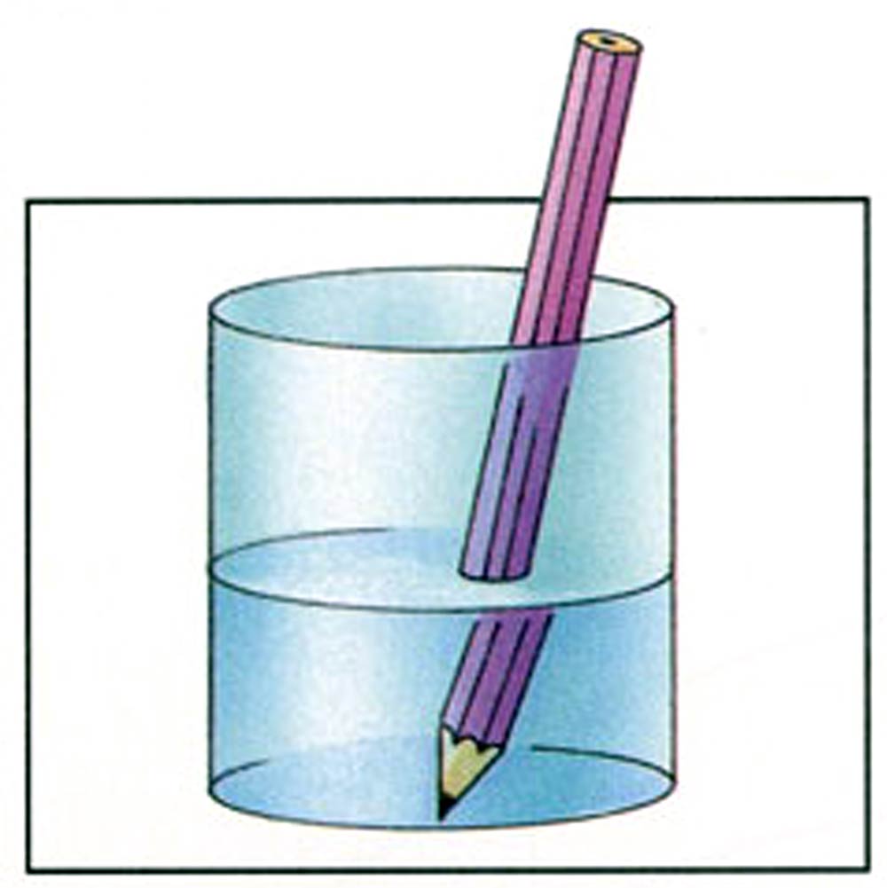
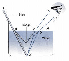
Consequence of refraction of light: Apparent Depth
A pool of water looks shallower than it really is. A straight object placed in water looks bent at the surfaces.
Refractive Index & Wavelength of Light
For visible light, the refractive indexes of most transparent medium decrease with increasing wavelength. Hence,
Spherical Mirror
The terms of spherical mirrors.
- The radius of Curvature (r): It is the distance between Pole and the Center of curvature.
- Center of Curvature (c): The Center of Curvature of a spherical mirror is the point in the center of the mirror which passes through the curve of the mirror and has the same tangent and curvature at that point.
- Aperture: It is a point from which the reflection of light actually happens.
- Pole (p): Pole is the midpoint of a mirror. It’s twice the focus.
- Focus: It is any point, where light rays parallel to the principal axis, will converge after reflecting from the mirror.
- Principal axis: An imaginary line passing through the optical center and the center of curvature of the spherical mirror.
- Focal Length: It is on the axis of a mirror where rays of light are parallel to the axis converge after reflection or refraction.
Spherical mirrors are of two types:
- Convex Mirror
- Concave Mirror
Concave Mirror
A concave mirror is also known as the converging mirror as in these type of mirrors light rays converge at a point after they strike and are getting reflecting back from the reflecting surface of the mirror.
Convex mirror
The convex mirror has a reflective surface that curves outward. These mirrors are “always” form virtual, erect and diminished regardless of the distance between the object and mirror.
When parallel rays of light strike the mirror, they are reflected in a way wherein they spread out or diverge. For this reason, a convex mirror is also a diverging mirror too. If these reflected rays are extended behind the mirror by dotted lines, they meet at a point.
This point is the focus of the convex mirror. The concave mirror is used in the vehicle so that the driver is aware of the vehicle coming from behind. They are also used in street light reflectors.
Assumptions and Sign Conventions
- The object is always taken on left side of the mirror.
- All distances are measured from the pole of the mirror.
- Distances actually transversed in the direction of light are taken as positive and those in the opposite direction are taken as negative.
- All the distances above the principal axis are considered to be positive and below the principal axis are considered to be negative.
Relation between Focal Length and Radius of Curvature
Radius of Curvature of a spherical mirror is 2 times focal length of that mirror.
f=R/2
R = 2f
From this it is clear that mirror lies midway between the pole and centre of curvature.
Mirror Formula
A mirror formula may be defined as the formula which gives the relationship between the distance of image v, distance of object u, and the focal length of a mirror. It may be written as,![]()
where, v = Distance of image from pole of mirror
u = Distance of object from pole of mirror
and, f = Focal length of the mirror
The mirror formula is applicable both in spherical mirrors (concave mirrors and convex mirrors) and in plane mirrors.
Image Formation For concave mirror:
| S.no. | Position of object | Position and nature of image formed |
| 1. | At infinity, | Image is real, inverted, small size and forms at principle focus.
|
| 2. | Beyond C, | Image is real, inverted and smaller size. Image is formed between F and C.
|
| 3. | At C, | Image is real, inverted and equal in size. Image is formed at C.
|
| 4. | Between F and C, | Image is real, inverted and magnified. Image is formed beyond C.
|
| 5. | At F, | Image is real, inverted and highly magnified. Image is formed at infinity.
|
| 6. | Between pole P and F, | Image is virtual, erect and magnified. Image is formed behind the mirror.
|
For Convex Mirror
| S.no. | Position of object | Position and nature of image formed |
| 1. | In front of a convex mirror at any position, | Image is erect, virtual, diminished and forms at other side of the object.
|
| 2. | If a converging beam is incident on convex mirror, | Image is real, inverted and in front ofmirror.
|
Questions and Answers :
Q1. An object is placed at a distance of 20 cm from a concave mirror of focal length 15 cm.At what distance from the mirror, should a screen be placed to get the sharp image.
Ans: here f = -15 cm
u = -20 cm
Determination of the position of image = ![]()
we get 1/v = 1/f – 1/u = -1/15 – (-1/20) = -1/15+ 1/20 = -1/60
hence v= -60 cm
so, the screen must be placed at a distance of 60 cm.
Q2. An object is placed at a long distance in front of a convex mirror of radius of curvature 30cm. State the position of its image.
here using sign convention
object distance u = ∞ (infinitive)
Radius of curvature = R = +30 cm (center of right of mirror)
Focal Length = f = R/2 = 15cm
Image distance v = ?
From mirror formula ![]()
we have 1/v = 1/f – 1/u
1/v = 1/15 – 1/∞
v= 15 cm
The image is formed at a distance 15 cm to the right of the mirror. The image lies at focus.
Refractive Indices for some common Gases
| Gas | Refractive Index – n – |
|---|---|
| Acetone | 1.001090 |
| Air | 1.000293 |
| Alcohol, ethyl | 1.000878 |
| Alcohol, methyl | 1.000586 |
| Ammonia | 1.000376 |
| Argon | 1.000281 |
| Benzene | 1.001762 |
| Bromine | 1.001132 |
| Carbon dioxide | 1.000449 |
| Carbon disulphide | 1.001481 |
| Carbon monoxide | 1.000338 |
| Chlorine | 1.000773 |
| Chloroform | 1.001450 |
| Ether, ethyl | 1.001533 |
| Ether, methyl | 1.000891 |
| Helium | 1.000035 |
| Hydrochloric acid | 1.000447 |
| Hydrogen | 1.000132 |
| Methane | 1.000444 |
| Nitric oxide | 1.000297 |
| Nitrogen | 1.000298 |
| Nitrous oxide | 1.000516 |
| Oxygen | 1.000271 |
| Pentane | 1.000686 |
| Sulphur dioxide | 1.000686 |
| Water vapor | 1.000261 |
Index of Refraction for common Liquids
| Fluid | Refractive Index – n – |
|---|---|
| Acetic Acid | 1.37 |
| Acetone | 1.36 |
| Alcohol, ethyl (ethanol) | 1.36 |
| Alcohol, methyl (methanol) | 1.33 |
| Alcohol, propyl | 1.38 |
| Aniline | 1.586 |
| Benzene | 1.501 |
| Benzyl benzoate | 1.568 |
| Carbon disulfide | 1.63 |
| Carbon tetrachloride | 1.46 |
| Chlorobenzene | 1.525 |
| Chloroform | 1.44 |
| Decane | 1.41 |
| Dodecane | 1.41 |
| Ether | 1.35 |
| Ethylene glycol | 1.43 |
| Ethyl salicylate | 1.523 |
| Ethyl cinnamate | 1.559 |
| Trichlorofluoromethane refrigerant R-11 | 1.37 |
| Dichlorodifluoromethanerefrigerant R-12 | 1.29 |
| Chlorodifluoromethane refrigerant R-22 | 1.26 |
| Furan | 1.47 |
| Glyserine (Glycerol) | 1.47 |
| Heptane | 1.38 |
| Hexane | 1.37 |
| Methyl salicylate | 1.538 |
| Methylene iodine | 1.737 |
| Milk | 1.35 |
| Octane | 1.40 |
| Oil, cedar | 1.516 |
| Oil, vegetable 50oC | 1.47 |
| Oil, oiive | 1.46 |
| Oil, turpentine | 1.47 |
| Paraldehyde | 1.405 |
| Parafin, liquid | 1.48 |
| Propane | 1.34 |
| Propylene | 1.36 |
| Propylene glycol | 1.43 |
| Quinoline | 1.627 |
| Toluene | 1.497 |
| Turpentine (wood) | 1.47 |
| Water | 1.333 |
Refractive Index of common solids
| Solid | Refractive Index – n – |
|---|---|
| Crown glass | 1.5 – 1.62 |
| Diamond | 2.417 |
| Flint glass | 1.57 – 1.75 |
| Ice | 1.31 |
| Plexiglas | 1.49 |
| Polystyrene | 1.59 |
| Salt | 1.52 |
Example
Q. Light travels from a rarer medium 1 to a denser medium 2. The angle of incidence and refraction are respectively 45° and 30°. Calculate the refractive index of second medium with respect to the first medium.
Ans: Given, angle of incidence, i = 45°
Angle of refraction, r = 30°
from relation, n= sin i/sin r
putting values, we get 2n1
2n1 = sin45°/sin 30° = 1.414
Lens Formula
The lens formula is a mathematical relationship between object distance , image distance and focal length of a spherical lens.
Where f is the focal length of the lens, u is the distance of the object from the lens and v is the distance the image is formed from the lens.
M=vu
The size of an object’s image is larger (or smaller) than the object itself by its magnification, M. The level of magnification is proportional to the ratio of v and u. An image that is double the size of the object would have magnification M=2.
The lens formula is a mathematical relationship between object distance (u), image distance (v) and focal length (f) of a spherical lens.
The lens formula is written as:-
1/f= 1/v -1/u
This formula is applicable for both, convex and concave lenses, whether the image formed is real or virtual.
Signs of “u”, “v” and “f”
“u” is always taken negative.
“f” is taken positive for convex lens and negative for concave lens.
“v” is taken positive for real image and negative for virtual image.
Human Eye
- The human eye is an organ which reacts to light and pressure.
- As a sense organ, the mammalian eye allows vision.
- Human eyes help to provide a three dimensional, moving image, normally coloured in daylight.

How The Eye Works
In a number of ways, the human eye works much like a digital camera:
- Light is focused primarily by the cornea — the clear front surface of the eye, which acts like a camera lens.
- The iris of the eye functions like the diaphragm of a camera, controlling the amount of light reaching the back of the eye by automatically adjusting the size of the pupil (aperture).
- The eye’s crystalline lens is located directly behind the pupil and further focuses light. Through a process called accommodation, this lens helps the eye automatically focus on near and approaching objects, like an autofocus camera lens.
- Light focused by the cornea and crystalline lens (and limited by the iris and pupil) then reaches the retina — the light-sensitive inner lining of the back of the eye. The retina acts like an electronic image sensor of a digital camera, converting optical images into electronic signals. The optic nerve then transmits these signals to the visual cortex — the part of the brain that controls our sense of sight.
Parts Of The Eye And structure
Cornea
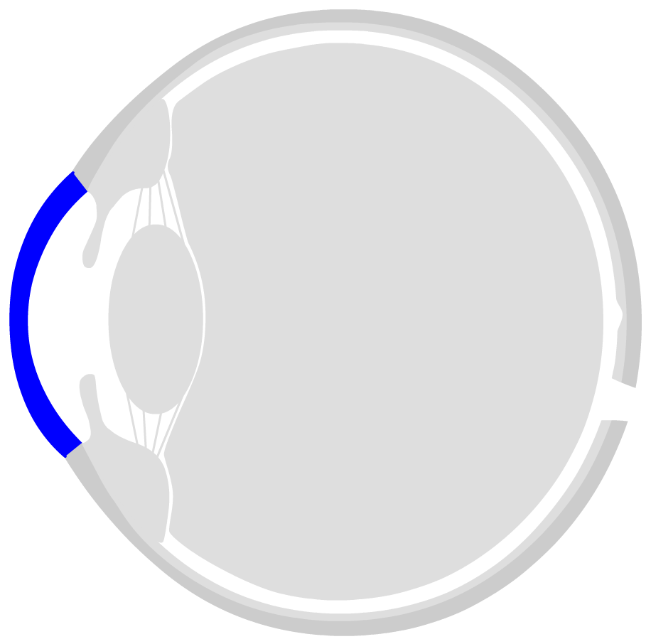
The front side of the eye is the cornea. The cornea is transparent and consists of six layers. The ring-shaped transition from the cornea to the sclera is called limbus (from Latin for “border”). With the help of the stem cells located there, the cornea is permanently renewed. It is slightly thinner in the centre than the outer areas. This is especially important in the case of eye lasers, when a part of the cornea is removed in order to optimize the refractive power. The curvature of the cornea refracts the light by about 45 dioptres. The cornea is covered with tear fluid, which is formed in the tear glands and serves to supply and protect the eye.
Anterior and posterior chamber, intraocular fluid
Behind the cornea is the anterior eye chamber, which is filled with intraocular fluid. It contains nutrients to supply the eye lens and cornea. In addition, immune factors are floating in intraocular fluid, which serve to render potentially damaging foreign bodies and germs harmlessly. It also helps to maintain a constant intraocular pressure. Behind the iris the posterior chamber of the eye begins. The intraocular fluid is produced and released at the ciliary processes. It then slowly flows through the pupil into the anterior chamber of the eye.
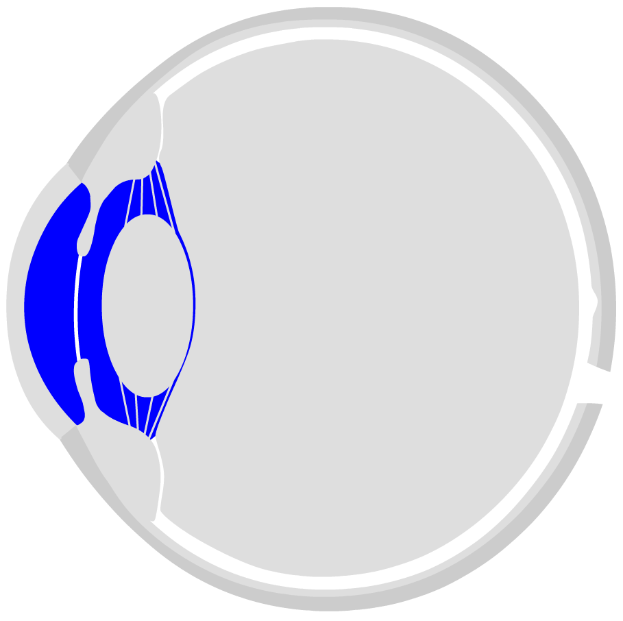
Iris
The iris is located in the center of the cornea. It consists of many fine muscle pathways that can contract or expand. The resulting round opening in the center is called the pupil. The darker it is, the more light is needed for vision – the pupil becomes correspondingly larger in darkness. In very bright light, the pupil is only small. The iris is (except for so-called albinos) coloured by certain pigments (blue, brown, green, grey or corresponding mixed values).
Lens
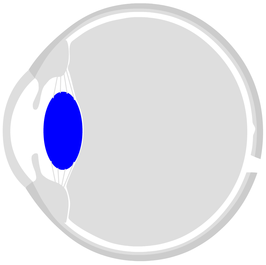
Behind the pupil is the eye lens (Phakos). It is responsible for about 15 dioptres of the refractive power, but it can change its refractive power. Thanks to this ability (so-called accommodation), the eye can see sharply both near and far. The eye lens is a kind of liquid sphere. They can be compared to a water-filled balloon. In the middle – on the so-called lens equator – the lens is hung up on the zonula fibres, which originate from the ciliary muscle. The lens fluid solidifies over the decades. It is thus the cause of widespread presbyopia. In addition, protein structures in the lens of the eye increasingly clump together over time, clouding the image. This deterioration in visual quality is also known as cataract. Often, the old lens is removed during cataract surgery and an artificial lens is simply inserted – which ensures a clear view even in old age.
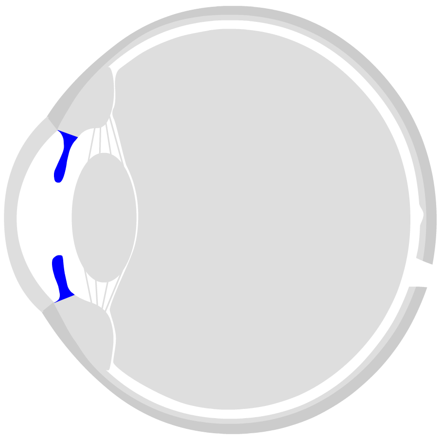
Ciliary muscle
The ciliary muscle is located behind the cornea in a ring-shaped shape inside the eye. It can actively influence the curvature of the eye lens. In a relaxed state, the lens is flat and drawn out – so you can see well in the distance. However, if the ciliary muscle tightens (contract tone), the diameter of the ring becomes smaller. The zonula fibres relax and the lens takes on a rather bulbous, spherical shape. This changes the refractive power of the lens so that you can see well in the vicinity. This process is called accommodation.
Vitreous chamber

The inner space of the eyeball is filled by the vitreous body. It consists of a gel-like clear liquid and is especially important for the stability of the eyeball: the liquid generates a pressure, the so-called intraocular pressure. This ensures that the surrounding layers do not peel off and collapse. In addition, without intraocular pressure, the eye would be much more sensitive to external pressure influences that affect the cornea from the outside. An abnormal intraocular pressure is the cause of many eye diseases, such as glaucoma.
The dioptric apparatus
All components through which the rays of light pass before they hit the retina have a dioptric effect. They are also called dioptric apparatus. The aqueous humor and the vitreous body are ideally almost transparent, so that there is hardly any measurable refraction of individual photons. The cornea and eye lens are responsible for the actual dioptric effect. The entire eye has a refractive power of approx. 59 dioptres (dpt), of which approx. 43 dpt (75%) is on the cornea and approx. 19 dpt (25%) on the eye lens (in a relaxed, non-accommodated state).
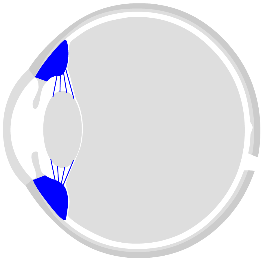
Sclera
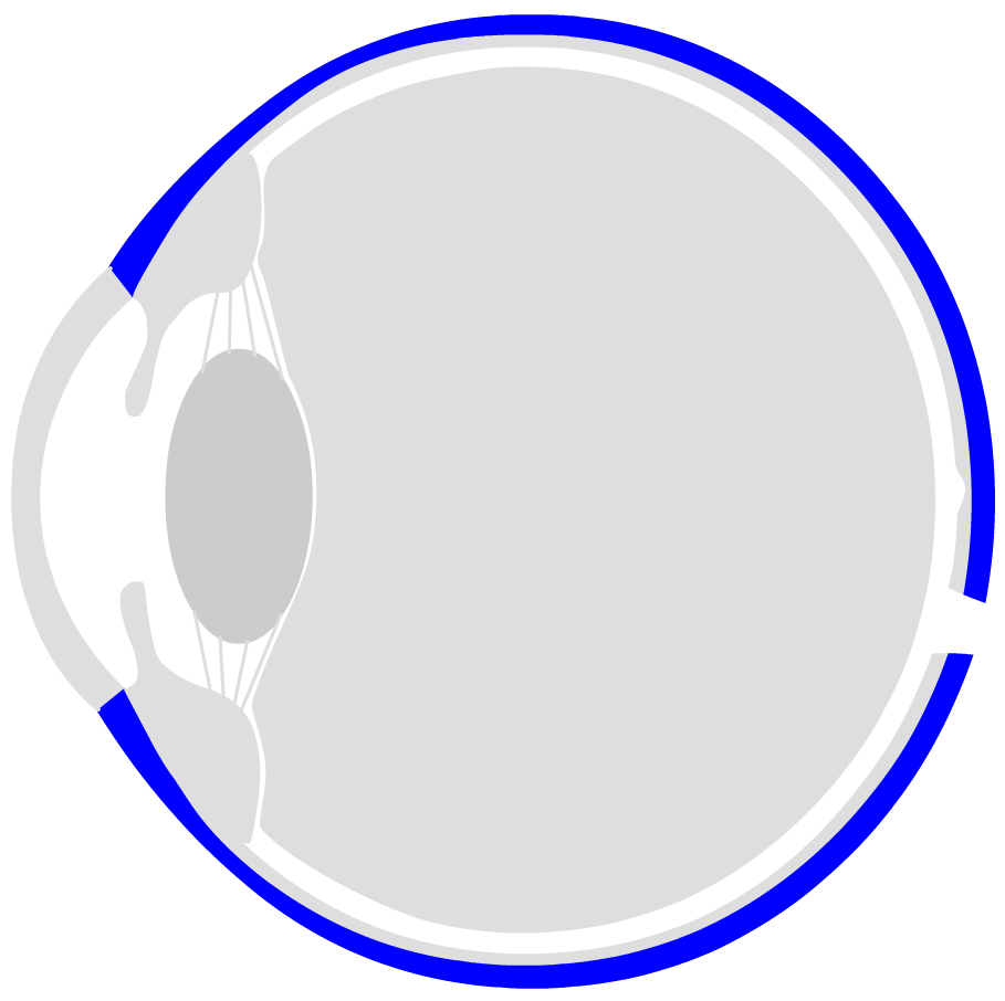
The eyeball is surrounded by three layers. The outer shell is called sclera. The dermis has a whitish colour – in the front, open part of the eye you can see it well. It encloses the eyeball almost completely and protects the eye. The dermis is interrupted only in two places: in the front by the circular, transparent cornea (Cornea) and in the back of the eye by the optic nerve coming from the inside of the eye.
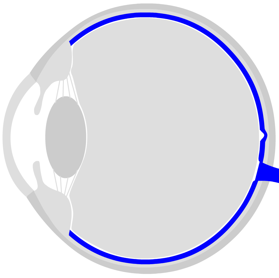
Choroid

Inside the protective sclera follows the choroid, which, as the name suggests, is permeated by numerous blood vessels and capillaries. The blood supplies the retina with nutrients and oxygen. The choroid is dark pigmented and ensures that unprocessed light is absorbed (instead of being reflected into the inside of the eye). The effect of the “red eyes on photos” is related to this: the flash is so intense that it brightens up the inner eye. The red blood vessels of the choroid are then visible in the photo.
Retina
The retina is located on the back / inside of the eye. It consists of different cell layers: the photoreceptors (sticks for chiaroscopy, cones for color vision) convert the light impulse into an electrical nerve impulse. The light information is bundled in so-called receptive fields, amplified and transmitted to the brain via the visual verve (visual pathway).
The actual “visual process” then takes place on the retina. The retina consists of a number of different cell types with very different tasks. First of all, the so-called sensory cells are important. They transform the light into an electrical impulse. How this works is explained on the page “How does seeing work?” described. There are two types of vision cells:
- the chopsticks (light-dark vision, active in twilight or darkness)
- the cones (responsible for colour vision)
Three different cone cells are required for color vision:
- Pins for red-visibility (approx. 46 % of all pins)
- Cones for green vision (approx. 46% of all cones)
- Cones for blue vision (approx. 8% of all cones)
The three cone types each react to light of different wavelengths. If a photon with a wavelength in the red region hits a red cone, then it “fires” an impulse at the following cells. The other two cone types remain inactive for a “red photon” (at least statistically seen). They react accordingly when photons arrive with their specific wavelength.
If one of these cone types is not properly formed due to a genetic defect, there is a color vision impairment or color blindness. See red-green weakness. The genetic abnormalities of the eye’s colour are:
- Protanomaly: Red vision weakness
- Protanopia: Red blindness
- Deuteranomaly: Green vision weakness
- Deuteranopia: Green blindness
- Tritanopia: Blue blindness
- Tritanomaly: Blauseh weakness
Further processing on the retina
The retina consists of a large number of other cells that process the electrical impulses sent by the visual cells. The visual information from adjacent regions is bundled, compared and enhanced in contrast. Roughly speaking, it can be said that only “new” and “relevant” information from the “image” is passed on to the brain. Many interesting optical illusions are based on the processing of visual information in the retina. This “filtering” of information is very effective and economical. Evolution has developed the eye in such a way that it consumes as little energy as possible. Logically, you don’t have to see everything to survive, but only what is important.
Stereoscopic vision
The pre-structured optical information is then transmitted to the brain via the optic nerve. The information is collected from the left and right eye and forwarded together. This is where the so-called “stereoscopic vision”is created. The information from the left and right eye is slightly different, since the angle of incidence is slightly different. From this difference, the brain can infer something like space. The spatial visual impression is thus created from the different information of the two eyes. Correctly, however, one has to say that the learned information such as perspective, proportions and so on have a greater share of the three-dimensional visual impression than stereoscopic vision.
Finally, the information reaches the brain via the optic nerve – and here it is distributed over large areas that are stored to varying degrees (via linked synapses of the individual nerve cells). Ultimately, this “neural pattern” is what we know as a visual image of reality. This pattern has been constantly developed and modified since the first day of opening the eyes. It is a mixture of visual memory and new visual impressions. Seeing is a living, dynamic process.
Defects Of The Eye
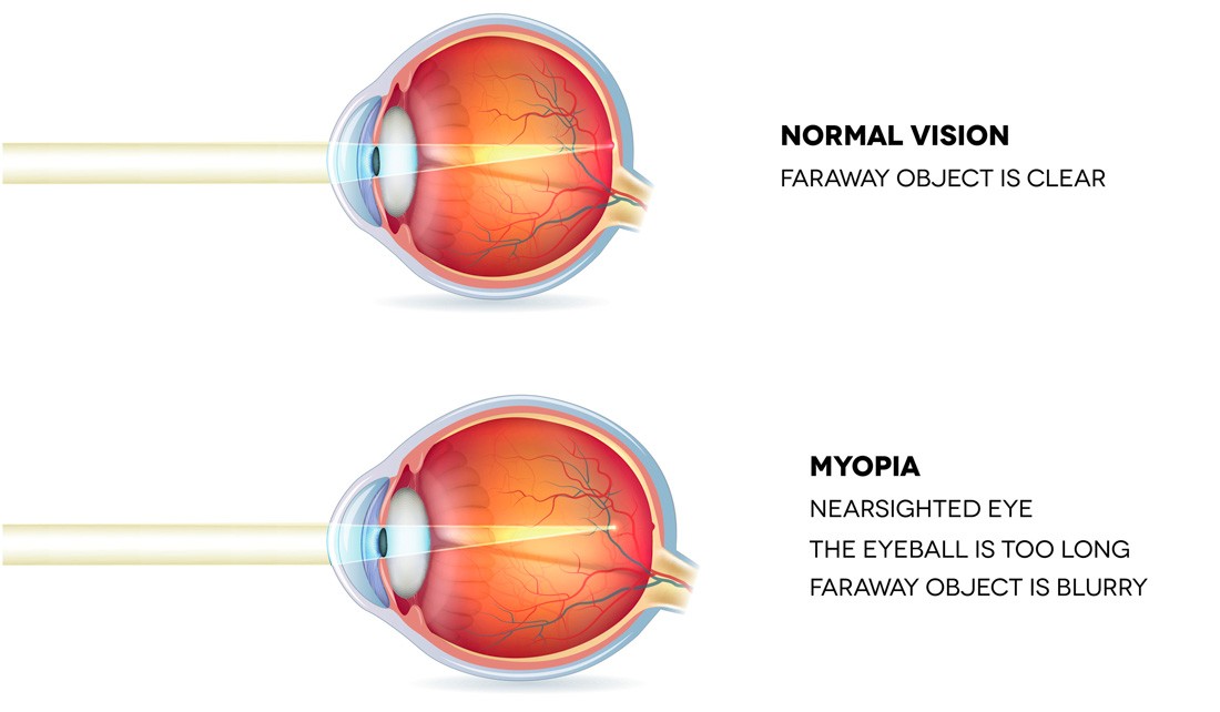
a. Myopia or Near-Sightedness
- Myopia is a defect of vision wherein far-off objects appear blurred and objects near are seen clearly.
- Since the eyeball is too long or the eye lens’s refractive power is too high; the image forms in front of the retina rather than forming on it.
- Correction of myopia can happen by wearing glasses/contacts made of concave lenses to help focus the image on the retina.

b. Hypermetropia or Longsightedness
- Hypermetropia is a defect of vision wherein there is difficulty in viewing objects that are near but one can view far objects easily.
- Since the eyeball is too short or eye lens’s refractive power is too weak hence the image instead is of being forming upon the retina, its forms behind the retina.
- Correction of hypermetropia can happen by wearing glasses/contacts containing convex lenses.
c. Cataract
- Cataract is the clouding of the lens, that prevents the formation of a clear, sharp image.
- A cataract forms when old cells after they die, stick in a capsule wherein with time a clouding over lens happens.
- Because of this clouding blurred images are formed.
- Correction of cataract can happen through a surgery.
- An artificial lens in place of the opaque lens is used after removing it via surgery.

d. Presbyopia or Old-age Longsightedness
- Presbyopia is a natural defect that occurs with the age. In presbyopia, the ciliary muscles become weak and are no longer able to adjust the eye lens.
- The eye muscles become so weak that no longer can a person see nearby objects clearly.
- The near point of a person with presbyopia is more than 25cm. Correction of presbyopia can happen by wearing bifocal glasses or Progressive Addition Lenses (PALs) wherein the upper portion of the lens contains concave lens and lower portion contains a convex lens.
- A person with presbyopia can also have just myopia or just hypermetropia.

e. Astigmatism
- Astigmatism is a defect wherein the light rays entering the eye do not focus light evenly to a single focal point on the retina but instead scatter away.
- The light rays in a way where some focus on the retina and some focus in front of or behind it.
- This happens because of non-uniform curvature of the cornea; resulting in a distorted or blurry vision at any distance.
- Correction of astigmatism can happen by using a special spherical cylindrical lens.

Power of Accommodation
- Power of accommodation is the process by which ciliary muscles function, to adjust the focal length of the eyes so that clear image forms on the retina.
- This varies far or nearby objects.
- For a normal eyesight, the power of accommodation is 4 dioptre.
Dispersion Of Prism
Prism
- It is a solid figure having two triangular bases and three rectangular surfaces and is the closed surface.
- The angle between each surface is the angle of the prism. In a prism, the opposite surfaces are equal surfaces and are parallel.
- There are two refracting surfaces which mean the surface where refraction of light takes place.
- We are not concerned about other faces.
Dispersion
- With the help of a narrow beam of light, a glass prism, and a white wall it is possible to produce the band of seven colors using white light.
- Keep this arrangement near the window.
- Place the glass prism in such manner that the sunlight through the window falls on one side of the prism and then on the white wall.

- You can see that the light reflected on the wall has several colors.
- The prism splits the white light into seven different colors.
- This splitting of white light into many colors is called as a dispersion of light.
- Dispersion is nothing but splitting of white light into its constituents colors.i.e into seven different colors.
- The seven colors are violet, indigo, blue, green, yellow, orange, and red (VIBGYOR).
- The pattern of color which is obtained is called as a spectrum.
- Sometimes in the rainbow, you may not see all the seven colors. This is because of the colors overlap each other.
What Causes Dispersion of Prism?
- Dispersion of prism takes place because white light entering the prism consists of so many different colors.
- Each of these different colors has a different wavelength.
- According to Cauchy’s formula, refractive index (μ) of a material depends upon wavelength (λ) and is given by,
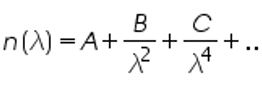
- where a, b, c are constants of the material.
- Since the wavelength of violet light is smaller than of the red light μv > μr, therefore the violet light has a larger angle than the red light. As a result, the dispersion of white light takes place on the second surface of the prism.
Atmospheric Refraction
Atmospheric refraction is the deviation of light or other electromagnetic wave from a straight line as it passes through the atmosphere due to the variation in air density as a function of height.
Examples of Atmospheric Refraction
a.Sunrise and Sunset

Due to the atmospheric refraction, we can see the sun 2 minutes before and after actual sunrise and sunset. The rays of light emitted by the sun are refracted towards the ground while travelling through the optically rarer layers of air in the atmosphere; when the Sun is slightly below the horizon. This results in making the sun appear slightly raised above the horizon and hence the sun is visible 2 minutes before and after actual sunrise and sunset.
b. Twinkling of Stars
After passing through the earth’s atmosphere having different layers of air with different optical densities, the rays of light coming from the stars finally reach our eyes. But, due to the change in the temperature conditions, the optical densities of different layers of air keep changing continuously. Because of which, the rays of light coming from a star are refracted to different degrees at different moments of time, and the path of refracted rays keeps changing. Hence, sometimes due to the amount of light refracted towards our eyes is more stars appear bright to us, on the other hand sometimes since less light is refracted towards our eyes, the stars appear dim to us. This gives us the twinkling of stars.
c. Mirage

In summers in desserts, due to atmospheric refraction is an optical illusion known as ‘Mirage’ occurs. During the mirage, an object such as a tree appears to be inverted and appears to be on the bank of a pond. On a hot summer day, since the layers of air near earth’s surface become hot, these layers act optically rarer medium.Whereas, the layers of air above the earth’s surface are cooler and therefore act as the optically denser medium. Light, therefore, refracts when it travels through a sudden transition between layers of cold and hot air.
Scattering of Light
- A part of light gets absorbed by the particles of any medium ahead of it’s following radiation in a particular direction when light travels from one medium to another medium.
- This is called as the ‘Scattering of Light’.
- During scattering of light; the light spreads in all directions.
Without a change in its wavelength, the absorption and re-emission of light energy occur; wherein the molecules of air smaller than the incident light’s wavelength absorb the incident light’s energy and a re-emit the light energy.
Scattered light’s ‘intensity’ is a function of the wavelength of the ray of light. I×1λ
Tyndall Effect

- Tyndall effect is the scattering of a beam of light as it passes through a colloid (a medium containing suspended particles like smoke or dust in a room) wherein the suspended particles scatter and reflect the beam of light, making it visible.
- What differentiates a colloid from a true solution is the size of the particles, i.e. the particle size for a colloid must be between 1-1000 nanometers.
- Tyndall Effect was named after the physicist John Tyndall after discovering it in the 19th century.
Why does the sky appear blue?
- When white light (sunlight) falls in the atmosphere, rays of light with longer wavelengths don’t get scattered by the air molecules.
- Since only blue light has the shortest wavelength, it is scattered by air molecules in the atmosphere resulting in the sky appearing blue.
Sun appears red at sunset and sunrise. Why?
- During the sunset and sunrise, since all the blue light is scattered away already and is out of our sight, the light reaching is red which has a longer wavelength.
- At sunrise the earth is rotating towards the sun.
- Similarly, during sunset, the earth is rotating away from the sun.
- During these times the sunlight has to travel at an angle and thus cover a longer distance through the atmosphere.
- It encounters more obstacles in its path.
- Most of the colours, like green and violet, get scattered before the light reaches the earth. Since red is scattered the least, it is this colour that we see as it reaches us.
During noontime, the sun is directly overhead and it appears white. This is because the sunlight has to cover a much lesser distance through the atmosphere and it faces less obstacles. Hence, it escapes a great deal of scattering.